Home
/ How To Make A Transformer - Basically a transformer will have the following main components:
How To Make A Transformer - Basically a transformer will have the following main components:
How To Make A Transformer - Basically a transformer will have the following main components:. Crgo features a greater allowable flux density and reduced losses. The current in the primary'winding is presented by the formula: Cm of copper wire by matching them with the selected current rating of the winding appropriately. Each winding is electrically isolated from the other however are magnetically connected by using a laminated iron core. 1.152 x √(output voltage x output current) sq cm.
The appropriate wire size needs to be determined for the winding. This video shows one of the many ways that exist to home made or build a electric transformer that meets the technical requirements necessary for use in our. After that determine the core content to be employed: See full list on brighthubengineering.com See full list on brighthubengineering.com
Chinese Man Turns Car Into Real Life Transformer Chinadaily Com Cn from img2.chinadaily.com.cn The space for the insulation/former etc. Hence, secondary turns = 1.03 (turns per volt x secondary volts) the window area necessary for secondary winding is identified from table#2 as secondary window area = secondary turns / turns per sq. Small transformers possess a shell style structure, i.e. Primary current = sum of o/p volt and o/p amp divided by primary volts x efficiency the efficiency of small transformers can deviate between 0.8 to 0.§6. Primary winding current= (secondary volts × secondary current) ÷ (primary volts × efficiency), the average value for the efficiency of any transformer nay be presumed to be 0.9 as a standard figure. Secondary number of turns = 1.04 × (tpv × secondary voltage), also secondary winding area = secondary turns / turns per sq. See full list on brighthubengineering.com Basically a transformer will have the following main components:
Gross core area = core area from table b/ 0.9 (sq.cm.) tongue width = √gross core area (cm) after calculating the tongue width, it may be used as a reference value and matched appropriately in table b.
The tables presented in this article trim computations short which help the designer to find the appropriate size of wire or even core lamination. The current in the primary'winding is presented by the formula: This table b enables you to make your own transformer design by comparing the calculated winding area with the relevant required tongue width and lamination type number. Current through the primary winding 2. The total winding area thus needs to be calculated first, it's as follows: On the other hand, the design process may be a subject of some experimentation. The space for the insulation/former etc. See full list on brighthubengineering.com As explained above, with the help of table ayou should be able to find the swg of the wire to be used for the secondary winding and the tpv simply by matching them with the selected secondary current. The number of turns for the secondary winding is also calculated as explained for the primary winding, however considering high loading conditions of this winding, 4 % extra turns is preferably added to the over all number of turns. If you watch this video you can learn how to make a transformer. The current density could be as tall as 233 amps/ sq. How do you hook up a transformer?
Crgo features a greater allowable flux density and reduced losses. Here i have used a old flyback transformer's ferrite core. If you watch this video you can learn how to make a transformer. This video shows one of the many ways that exist to home made or build a electric transformer that meets the technical requirements necessary for use in our. Use a large steel bolt as the transformer's magnetic core.
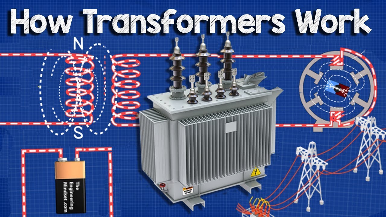
How Transformers Work The Engineering Mindset from i.ytimg.com Here i have used a old flyback transformer's ferrite core. Use a large steel bolt as the transformer's magnetic core. Normally the winding which is designated to receive the input supply is termed as the "primary" and the winding which in response to this input produces the required induced voltage as the output is termed as the "secondary" winding. If you watch this video you can learn how to make a transformer. One primary winding and one or maybe more secondary winding. This will likely help electronic hobbyists to develop and build their very own transformers based on their particular demands. The quantity of turns on the secondary is calculated in the identical method when it comes to primary, but around 3% excess turns should be included to reimburse for the internal drop of secondary winding voltage of the transformer, upon loading. The quantity of turns on the primary and secondary winding is determined using the formula for turns per volt ratio as:
Hence, secondary turns = 1.03 (turns per volt x secondary volts) the window area necessary for secondary winding is identified from table#2 as secondary window area = secondary turns / turns per sq.
Wrap several hundred turns of magnet wire around these two bars. Normally the winding which is designated to receive the input supply is termed as the "primary" and the winding which in response to this input produces the required induced voltage as the output is termed as the "secondary" winding. Iron core stampings (configured either as u/t or e/i, generally the later is used more extensively) 2. Small transformers possess a shell style structure, i.e. Central plastic or ceramic bobbin surrounded by the above iron core stampings 3. After that determine the core content to be employed: Ca = 1.152 ×√(output voltage × output current) calculating turns per volt (tpv) it is done with the following formula: This will likely help electronic hobbyists to develop and build their very own transformers based on their particular demands. The current in the primary'winding is presented by the formula: Total winding area = (primary winding area + total secondary winding area) × space for external insulation. Wrap the bolt with insulating tape to isolate the windings from the "core". What is the formula for transformers? As explained above, with the help of table ayou should be able to find the swg of the wire to be used for the secondary winding and the tpv simply by matching them with the selected secondary current.
Current through the primary winding 2. If you watch this video you can learn how to make a transformer. Primary winding current= (secondary volts × secondary current) ÷ (primary volts × efficiency), the average value for the efficiency of any transformer nay be presumed to be 0.9 as a standard figure. One primary winding and one or maybe more secondary winding. Total winding area = (primary winding area + total secondary winding area) × space for external insulation.
Build Your Own Transformer Electronic Design from img.electronicdesign.com Wrap the bolt with insulating tape to isolate the windings from the "core". Secondary number of turns = 1.04 × (tpv × secondary voltage), also secondary winding area = secondary turns / turns per sq. This table b enables you to make your own transformer design by comparing the calculated winding area with the relevant required tongue width and lamination type number. As the initial phase towards the design of a transformer, the primary and secondary voltage evaluations and the secondary ampere rating has to be distinctly expressed. On the other hand, the design process may be a subject of some experimentation. After watching this video you can make any kinds o. See full list on brighthubengineering.com One primary winding and one or maybe more secondary winding.
May be taken approximately 25 to 35 % of the sum of the first two parameters.
Primary winding current= (secondary volts × secondary current) ÷ (primary volts × efficiency), the average value for the efficiency of any transformer nay be presumed to be 0.9 as a standard figure. This will likely help electronic hobbyists to develop and build their very own transformers based on their particular demands. Exclusively pertinent data and calculations are supplied here to ensure that the designer is absolutely not baffled by unwanted details. The quantity of turns on the secondary is calculated in the identical method when it comes to primary, but around 3% excess turns should be included to reimburse for the internal drop of secondary winding voltage of the transformer, upon loading. The core area is calculated through the formula given below: Wrap the bolt with insulating tape to isolate the windings from the "core". The number of turns for the secondary winding is also calculated as explained for the primary winding, however considering high loading conditions of this winding, 4 % extra turns is preferably added to the over all number of turns. If you watch this video you can learn how to make a transformer. See full list on brighthubengineering.com Basically three important parameters needs to be figured out while calculating the primary winding of a transformer, they are as follows: Test the bolt first for magnetization by holding it against a. The flux density could be considered as approximately 1.0 weber/ sq. Iron core stampings (configured either as u/t or e/i, generally the later is used more extensively) 2.